[1]
The invention relates to a segmented blade, especially a diamond blade with a steel blade and distributed over the circumference of the base blade cutting segments, with the main blade section defining a central level and between two cutting segments each segment remains a gap. The invention also relates to a method for manufacturing such a blade.
[2]
These blades are generally known in great variety. As diamond blades they have a particularly high hardness and cutting ability. The particular hardness is achieved primarily through applied to the cutting of the diamond cutting industry segments. Most diamond blades have a metal body, called the master sheet, and a plurality of cutting segments that carry the abrasive trimming in the form of industrial diamonds. The more or less large segmentation contributes mainly to cool the tool. Diamond blades are used in particular for the processing of concrete and natural stone. For processing fibrous plastics they are so far used only conditionally, since efforts to enforce the segment gaps when cutting such materials.
[3]
The DE 35 04 343 A1 relates to a blade which can be used for the cutting of natural stones. Here, a master sheet and several distributed around the circumference of the counterfoil attached cutting segments is provided. In order to increase the cutting speed and to reduce the base blade diameter, the width of the cutting segments is equal to 1 / n of the width of the counterfoil selected plus the free section, wherein n is 2 or larger and the immediately successive cutting segments are arranged at Its width radially offset from one another.
[4]
Previously known cutting discs have a shape defined by the thickness of the base blade respectively mean width of the cutting segments which is limited to the range of a few millimeters. For cutting wider notches, particularly of more than 5 mm in width, the well-known cut-off wheels are not suited, so that scores have to be prepared with appropriate cutting tools mostly. In relation to milling discs however are expensive to purchase and to operate.
[5]
The object of the present invention is now to propose a cut-off wheel, which offers a high safety against overheating and zusetzender segment gaps in enlarged section width. It is also an object of the invention is a simple, to be implemented method for producing such a blade to create.
[6]
These objects are achieved by the blade having the features of claim 1 and method claim 7. Advantageous embodiments are stated in the respective dependent claims.
[7]
While lying in the known blades, the blades of the cutting segments has, in the middle section plane, it is the essential idea of the invention, to arrange individual cutting segments of the segmented blade so that their cutting edge respectively cutting edge is offset from the middle section plane somewhat. It is, of course, for avoiding imbalances particularly advantageous if the displacement is done in symmetry with respect to the central sectional plane. A very important advantage of this staggered arrangement of individual cutting segments lies in the increase of the cutting width, depending on the arrangement around the two to three times. In this way cuts can be made with these discs, and for which a cutting tool was needed previously. In order to save cost and simplifies the fabrication of such cuts.
[8]
A special advantage of these discs is that they are comparatively less hot when cutting and hardly increase. For this reason, materials can be cut with blades that were not available before this type of treatment. So it has been found that, for example, even fiber materials such as plastics, or cutting discs for a particularly problematic material can be cut easily now. This displacement of the cutting edges can be provided in all sizes of blades. It is especially advantageous when used for cutting discs of size between 1 mm and 3 mm, which have an appropriate number of cutting segments.
[9]
In terms of cutting efficiency and ease of production, it is particularly advantageous if the offset is accomplished in a deflection of the cutting segments from the middle section plane, so that the cutting edges, respectively, the cutting edges of the cutting segments of the middle section plane are offset with respect to parallel at a certain offset amount . According to the invention the deflection out in a bend of the blades carrying cutting segments from the middle section plane.
[10]
In an advantageous embodiment, not only a selected few, but all cutting edges are arranged offset with respect to one another when the cutting edges of adjacent cutting segments are in different cutting planes. Of such enriched discs offer the highest safety against overheating and zusetzender segment gaps.
[11]
As the offset is always designed so it is particularly advantageous if not essential, that the cut edges of circumferentially spaced cutting segments are arranged with respect to the extent of the cutting width gaps, as all cut edges to fill the entire section width in total. This is necessary so that when cutting is not a web remains on average, which is caught by any of the cutting segments.
[12]
A particularly advantageous design of the offset is when the cutting planes, and thus the cutting edges of the cutting segments are arranged crossed. In this case, the sectional planes are alternately once with and once the central sectional plane. With such a pattern can be folded offset the average width of a segmented blade on the condition of the whereabouts of a minimal overlap in principle to almost double. A further increase in the width of cut is possible, that the cutting edges of the cutting segments in more than two cutting planes are arranged, for example stepped. With three levels could be achieved according to an almost three-fold section width, not necessarily a stepped arrangement must be chosen.
[13]
The invention is based on the 1 to 4 explains in more detail. Shown
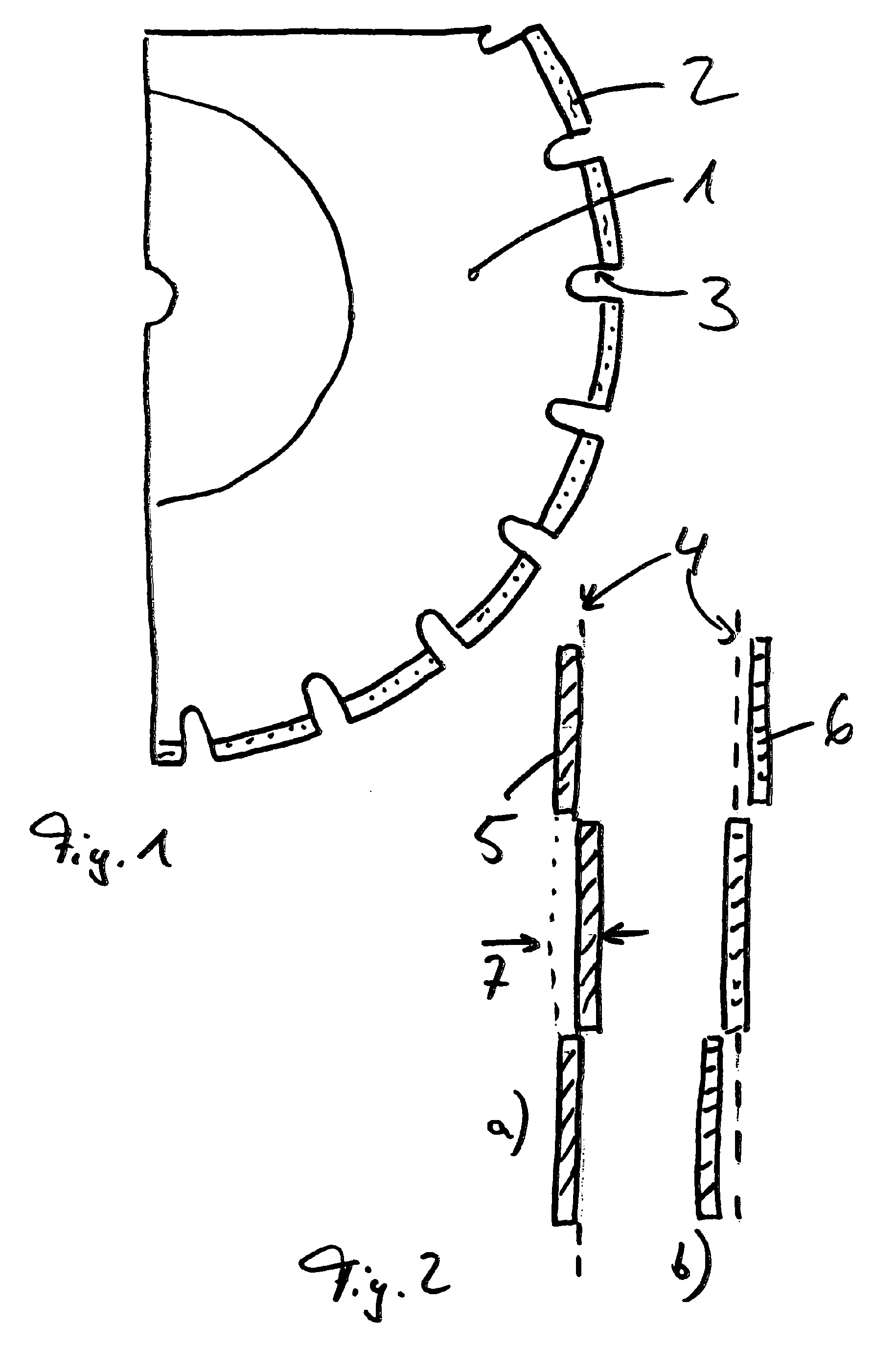
Figure 1
a view of a blade,
Figure 2:
a section along the cutting edge,
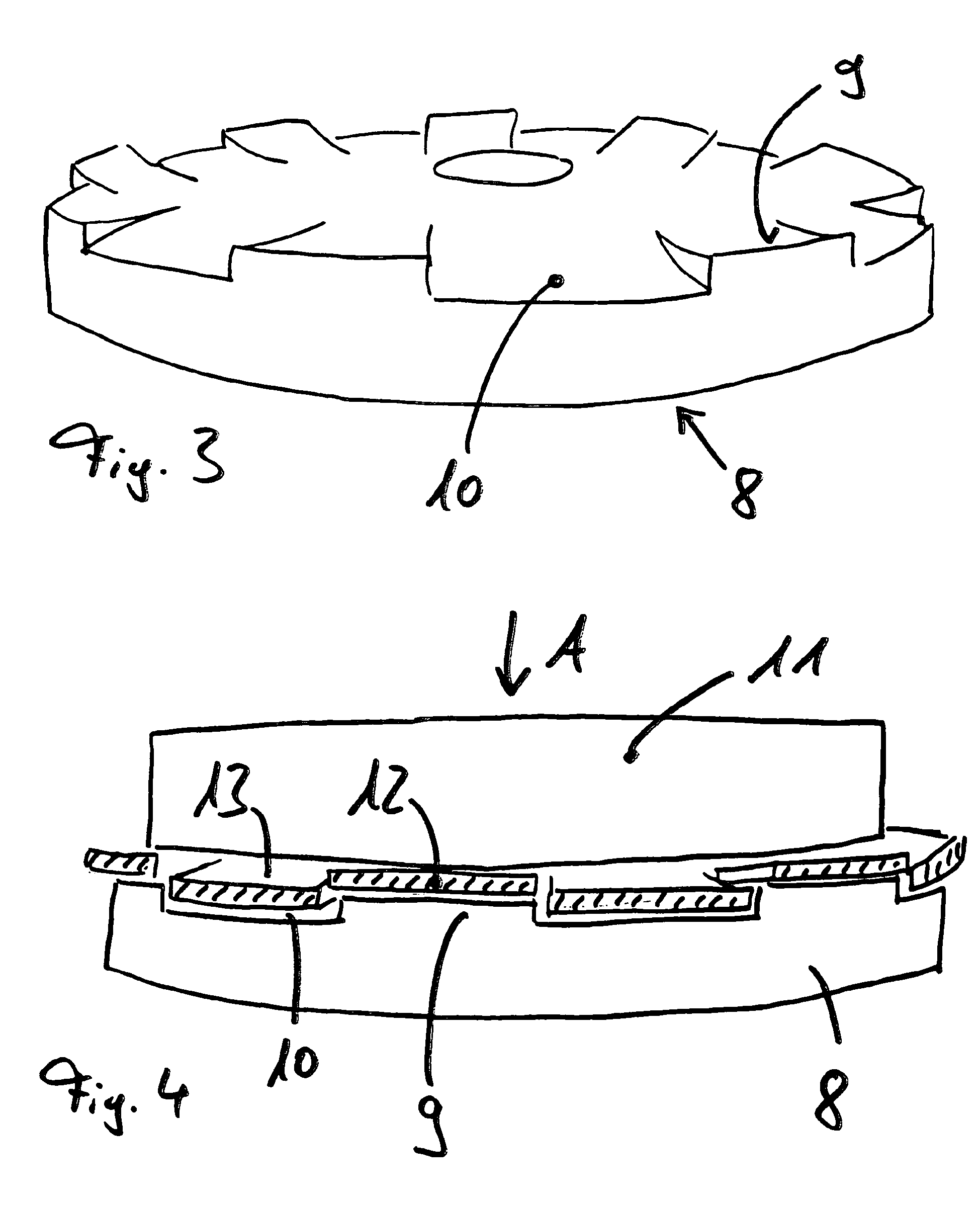
Figure 3:
an embossing die to manufacture the blade and
Figure 4:
a pressed between stamping mold and die cutting plate.
[14]
In Figure 1 is a segment of a segmented diamond blade shown having a central master sheet 1 of hardened steel and the circumference of the base blade cutting segments distributed 1 second The cutting diamond segments 2 are occupied, and applied to the periphery by means of a suitable welding method. Each segment is a gap 3, which extends into the master sheet 1 into between the cutting segments second The center plane of the base blade defines a central cutting plane ("0" line) 4, in the Figure 2 is shown as a broken line.
[15]
As seen in Figures 2a and 2b be seen, the cutting edges 5 of the cutting segments are arranged offset from the middle section plane 4. The cutting edges 5 of the cutting segments by Figure 2a insofar arranged interlaced as their cutting the broken line 5, below and above the central section plane alternately left and right. However, the cutting of the cutting segments are 6 to Figure 2b disposed stepwise in three cutting planes, wherein the average edge 6a located in the middle section plane 4 and the other two cutting edges adjacent left and right. In both embodiments according to Figures 2a and 2b are the cutting edges of the cutting segments have in various sectional planes and with respect to the central section on a parallel plane offset. In addition, the cutting edges distributed over the periphery of the cutting members with respect to the cutting width 7 are arranged without gaps. That is, the sectional planes directly to the "0" line are respectively have a small overlap.
[16]
In order to provide for this offset, the cutting edges of the cutting segments after the method to be described below from the middle section plane are bent. The basis of the method used an embossing mold 8, after the example Figure 3 is circular and distributed over the circumference and ski jump like having upwardly projecting bending conditions ninth Between the bending supports 9, a gap 10 remains similar width. When manufacturing such a blade is placed on the embossed surface mold 8 in that each second cutting segment rests on one of the flexure supports 9. The other cutting segments extend beyond the spaces where not deformed blade.
[17]
As shown in Figure 4 shows the applied blade is subsequently pressurized in a pressing process by a punch 11 in the direction of arrow A against the embossing die 8, so that the blade is pressed in its entirety downwards in the coining die 8, while the bearing on the flexure supports 9 cutting segments 12 " above "remain. The other cutter segments 13 are pressed into the respective intermediate space 10.
[18]
To this step, is not bent in cutting segments 13 also deflect the side curved blade is taken out from the mold, inverted and placed pressurized accordingly. This step may be avoided if the die is formed as a kind of stamping die counterpart in the opposite direction and having raised bending conditions which intervene during the pressing operation in the intermediate spaces between each two bending conditions of the die.
Previous:Diamond saw blade edging tool Next:Diamond cutting blade for defective stone materials
Thank you for your interest in the above content, please leave us inquiry, you can expect a response within 24 hours.
Required fields are marked *
|
|
|
|